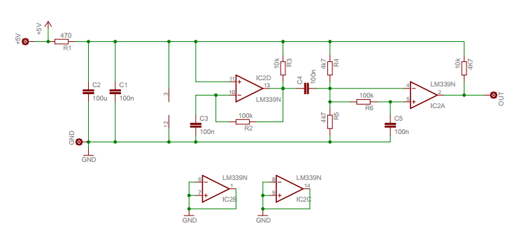
Schematic (based on XR232USB)
Board layout in Eagle:
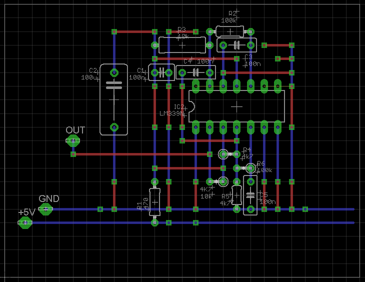
Eagle files: eagle.zip
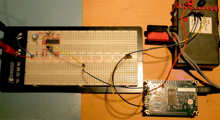
Red traces are wires, blue traces are the connections of the breadboard. This is the test setup, with a DE0-Nano and a TTL to RS232 serial converter:
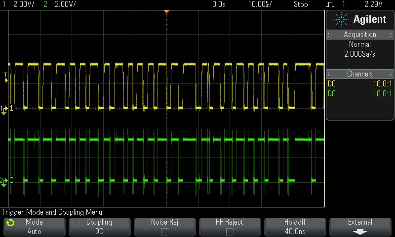
Yellow trace is the OUT signal, green trace is the sampled output GPIO_2(2) of the FPGA. Running:
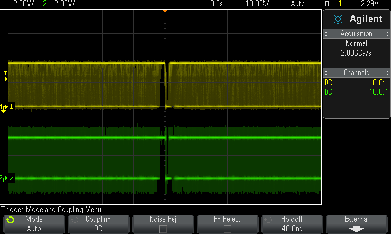
Stopped:
The DE0-Nano project with synthesized SOF file: DE0_NANO.zip
VHDL source code: main.vhd
Generated random data: random.bin and Diehard result: random.txt
