
The idea of the mailbox detector is to detect the movement of a mailbox slid for a "you've got mail" notification. Farnell sent me some of the MRF24J40MA modules for wireless communication (see this Farnell page for other nice products from Microchip). There are two important datasheets: First the datasheet of the RF transceiver module. You'll need this for the pins and dimension of the modules. And then there is the datasheet of the MRF24J40 chip itself, with a description of all registers and how to use it.
This was a first breadboard setup for testing the RF transceivers:
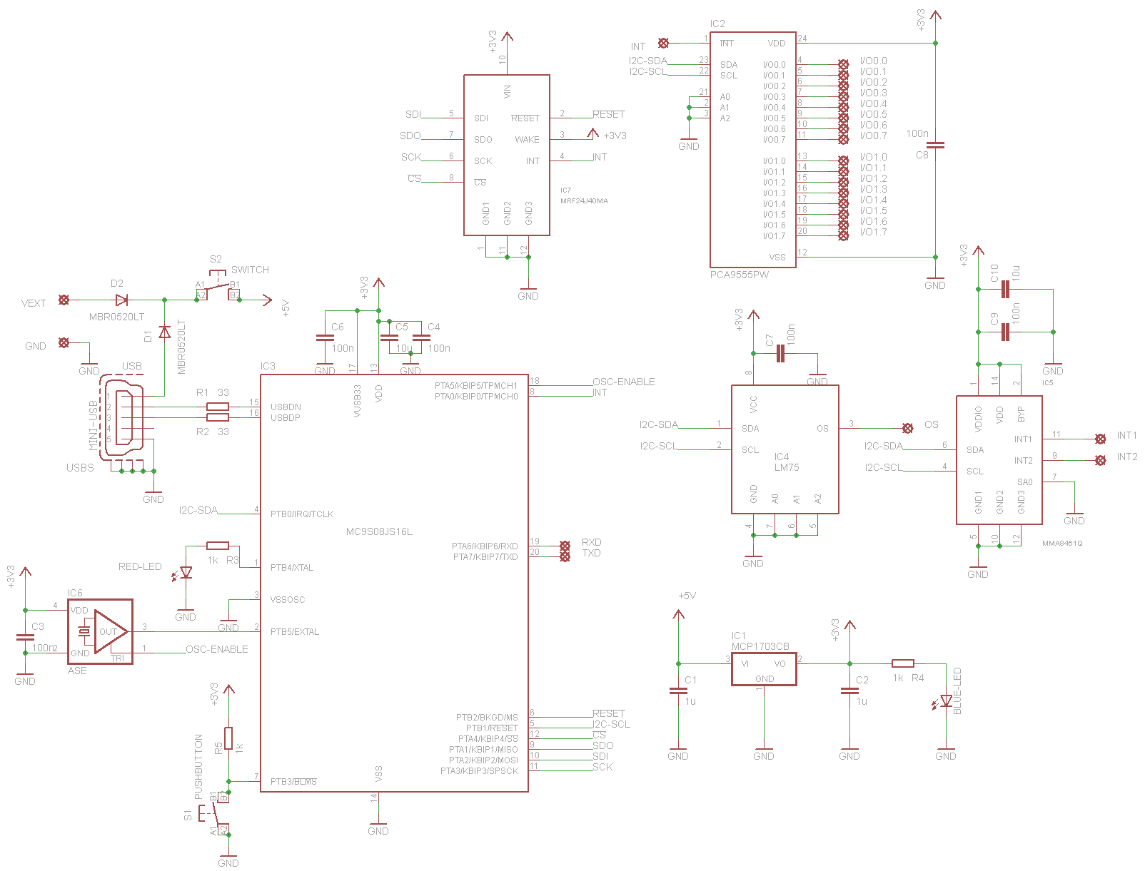
For the movement detection I planned to use the MMA8451Q accelerometer. An additional feature could be a temperature logger, so I added a LM75. And for more IO pins there is a PCA9555 port expander. This is the schematic:
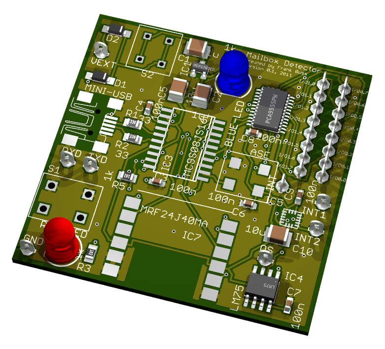
Rendered in Eagle 3D:
Eagle files: mailbox.zip
The PCBs are from ITead studio. They have a special offer: 10 PCBs, 2 layer, up to 5 cm x 5 cm for $9.90, silk screen etc. all included. The quality is really good, two PCBs populated:
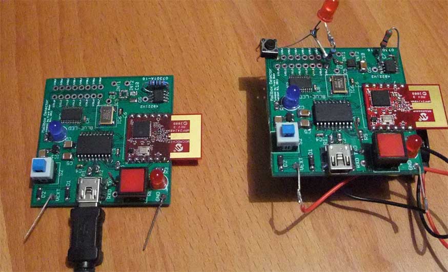
There is an extra 1.2 k pullup resistor on SDA, which I forgot in the schematic, but the rest worked without problems. The left module is connected to the PC and on the wireless right module I've hot-glued a 9 V battery at the bottom of the PCB.
Soldering the QFN accelerometer chip was a bit tricky, hot air is very useful for it, as shown in this video:
After unsoldering it once with the hot air, because not all connections were soldered, I got it and now it works.
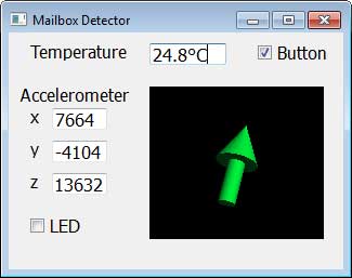
For testing it on the PC, I've written a small Qt program, which shows the state of one button on the GPIO chip of the wireless module, the temperature and where you can turn on the LED. The orientation of the module, as measured by the 3-axis accelerometer, is displayed as an OpenGL arrow:
A demonstration of the setup:
As you can see, the orientation test works just for less than 90° but this is not a fault of the sensor, but I have to improve the calculation. And the temperature is not really that high in my room, I guess there is another bug, or self heating of the circuit.
The software for the RF module is based on this software. I've even simplified it a bit more. The module works in promiscuous mode, which means it receives any data on the selected channel. The communication doesn't use any high level protocol like ZigBee, just raw packets. This is the firmware and Qt project, with source code: bidirectional.zip . The final mailbox detector needs just one direction, but this bidirectional implementation could be used for other interesting projects.
The datasheet says the range of the MRF24J40MA RF transceiver is up to 400 ft (122 m). I've tried it and it was about 65 ft. (20 m), but this was not on an open area, but an urban canyon and maybe the mounting of the module needs more space for the antenna. Inside the house it works without problems through multiple walls and even from inside a metal mailbox and through a wall to the receiver in 5 m distance.
The current consumption was 30 mA @ 3.3 V, nearly the same for sending and receiving. In sleep mode it can be reduced to some μA, but looks like I didn't managed to program the registers correctly so far, I was not able to put the module to sleep mode. If sending each minute a telegram, a battery should last many months when using the sleep mode.
Next step will be a new and smaller PCB for the wireless detector side. The wireless module can operate down to 2.4 V, which allows to use a CR2012 battery without a voltage regulator, which should reduce the current consumption even more.
The MRF24J40 transceiver implements the IEEE 802.15.4-2003 standard. On top of this you can implement protocols to setup a network with multiple modules. Microchip provides free libraries for their proprietary MiWi™ protocol and there are commercially libraries for ZigBee®.
